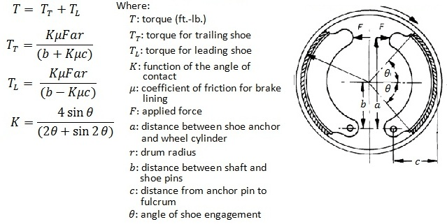
The power is then given by. Internal Drum Shoe Brake Design Equations.
Mechanical Brakes Selection Guide Types Features Applications Engineering360
Basis of Brake Calculation Basic braking calculations are derived from simple.

. Force on each brake drum F4 36449 N Area of the shoe brake in contact with brake drum 2 9423 30 106 565 103 Pressure on the brake drum FA 3645 565 103 0645 MPa To calculate the stress in the Brake Drum by the application of pressure. The backing plate provides a base for the other. Drum diameter reel diameter etc The brake will need to overcome this load before it can start to slow down the machine.
These procedures are discussed in Chapter 13. PC-BRAKE FACTOR software computes the brake factor of many different drum brake designs. They must be able to hold the aircraft back at full static engine run-up provide adequate control during ground taxi operations and be able to effectively stop the aircraft during landing and roll-out.
In order to calculate the power we need to know the brake on time. R Brake drum the drum has an internal friction surface for the shoes to rub against. Compared to a brake rotor a drum has significantly less contact area shown in Figure 12-5.
Drum calculations Parameter required Maximum load 15 kN Diameter of rope 14 mm Length of rope 50000mm Calculation a Diameter of drum Ddrum ratio between 20 to 25 x drope 20 x 14 280 mm b Groove radius r 053 x d 053 x 14mm 74mm c Groove diameter d groove radius x 2 74mm x 2 148mm d Pitch diameter. 31 Brake Factor Calculation. Estimation of accurate brake torque under varying conditions is predominantly the function of friction coefficient at the shoedrum interface.
For example for a lining-drum friction. The suitable brake torque at the shoedrum interface is the prerequisite of the active safety control. V peripheral velocity of drum.
The overall brake performance due to drum type foundation brake can be attributed to two criteria. WHEEL CYLINDER Wheel cylinder or caliper pistons. If the thickness to diameter ratio tD ratio.
Phosphate water-based detergent to wash the brake drum or rotor and other brake parts. DRUM BRAKE SYSTEM F ma. F coefficient of friction.
Aircraft brake systems perform multiple functions. Brake Calculations There are many books on brake systems but if you need to find a formula for something in particular you never can. M f fdN r ccosθ fp max.
Drum Brake Calculation Pdf Brake Vehicles Produced between 1906 through 1914. Brake factor computer software input and out put diagrams are illustrated for a typical S-cam-brake design in Figures 2 and 3. The green line represents the total brake factor of the leading-trailing S-cam brake.
Drum brake the value of the brake factor for this existing drum brake is. 𝟒 𝐢 𝛉 𝐱 𝟒 𝛉 𝛉 𝛉 𝛉 The torque applied to the drum by the brake shoe is the sum of the. Brake Design and Safety 2nd edition by Ruldolf Limpert.
3 Design Manual for Winch Systems Design basis Nomenclature Design basis Lifting load m h t Lifting speed v hmmin Lifting height H m Number of fixed deflection sheaves between drum and hoist or moving part n u - Required service life t h Number of winding layers on a drum n l - Number of parallel hoists or ropes reeved on a drum n. Drum brake system of passenger car is used. The solution should be applied with low pressure to prevent dust from becoming airborne.
Br sinθ max θ 2 sinθ r c cosθdθ θ 1 𝐱. Larger diameter pistons than the master cylinder piston and In the design calculation clearly illustrates the contact force a power booster to increase the input force or pedal force. These calculation are based on that given in the following reference.
VEHICLE DATA REQUIRED FOR CALCULATIONS GVW -Laden Front Axle weight Kg if provided 12592 Calculated 12592 Rear. We will look at each of these functions separately. The extracted friction coefficient has been used in the antilock braking.
2 shows the brake test rig that has currently been developed. Foundation brake is examined with regard to variation in the brake factor BF. Drum brakes depending on certain advantages discussed below.
Brake factor computer software input and out put diagrams are illustrated for a typical S-cam-brake design in Figures 2 and 3. It is assumed that the out of balance opposes the action of the brake. Depending on the position of rotor the braking system is of two types - Inboard Braking System and Outboard braking system.
A drum brake is a brake that uses friction caused by a set of shoes or pads that press against a rotating drum-shaped part called a brake drum. Important to understand action force and friction force on the disc brake new material how disc brake works more efficiently which can help to reduce the accident that may happen in each day6 IV. This is the average power the peak power at the onset of braking is double this.
Ac contact area in². Most of the vehicles use hydraulic braking system while some light vehicles such as bicycles use brake wires. Double Shoe Brake.
Allow the solution to flow between the brake drum and the brake support or the brake rotor and caliper. 1 dimensional design parameters of foundation brake and 2 friction between drum and lining 3. 312 Chapter 12t Drum Brake System Principles are used when working on the brake system.
The braking torque friction head losses through the brake When the brake pedal is depressed the. If the load is at rest the static brake. The moment M f of the frictional forcef𝑁 about the hinge pin at A is.
Mechanics and Machines Calculations Menu. DESIGN CALCULATION OF DISC BREAK ROTOR Here presenting the work for disc brake of MARUTI Company for stress reduction studies. Dry Disc Temperature Rise.
Based on the brake factor calculation derived by Mahmoud 13 for the simplex. P average contact pressure. Intent Design is a global technology enterprise providing product engineering design and.
Maximum brake force calculations for Drum Brakes Anirudh L Subramanyam Sandeep Banik The maximum brake force that can be generated on application of drum brakes are a. DESIGN AND DEVELOPMENT OF BRAKE TEST RIG Drum brake test rig is designed to provide the necessary rotation speed and applied pressure to the braking applications. Full PDF Package Download Full PDF Package.
Design requirements R BRAKE FORCE AT FRONT BRAKE FORCE DISTRIBUTION DIAGRAM UNLADEN CONDITION LADEN CONDITION. In an Inboard braking system the rotor brake disc. Intent Design Pvt Ltd.
The term drum brake usually means a brake in which shoes press on the inner surface of the drum. The relation between both factors is formulized as brake factor BF. The equations needed to design a braking system are not difficult to derive but this page is a reference to most of them.
BRAKE SYSTEM DESIGN AND THEORY. The wheel hub and brake assembly components should be. Brake Design and Safety 2nd edition by Ruldolf Limpert.
Heat Generated p Ac f V 778 Btumin Where.

Drum Brake Calculation Pdf Brake Vehicles
2

Brake Design And Calculation Pdf Brake Vehicle Technology
Brake Design And Calculation Pdfcoffee Com
2

Pdf Detailed Strength Analyses Of Drum Brakes Used In Light And Heavy Duty Trucks
2
Internal Drum Shoe Brake Design Equations And Calculator
0 comments
Post a Comment